Grease in sewerage systems causes problems, both mechanical, in terms of the clogging of pipes, and hygienic, i.e., foul odours. It also causes problems for the entire treatment process in wastewater treatment plants, where it impairs the sedimentation characteristics of sludge and subsequently the efficiency and outflow parameters.
The grease traps are used for precipitation and the capturing of grease that flows away in wastewater from kitchens, food-processing, and meat-processing plants, in order to protect sewerage systems and their equipment from clogging or sticking.
ASIO, spol. s r.o. uses many types of these devices. The selection of the optimum device depends on the type of grease, its quantity, the flow volume of wastewater, etc. For example, for low volumes, simpler devices can be used that usually offer lower efficiency, and conversely, for higher volumes, devices with higher efficiency are specified, which also represents more complex technology and design. The grease traps are designed in accordance with the ČSN EN 1825-1 standards, in the following versions, based on the type of material – polypropylene, polyethylene, and stainless steel. The traps bear the “CE” conformity symbol.
Types and designs of grease traps:
-
AS-FAKU ER/FR - rectangular, designed to be buried in the ground
-
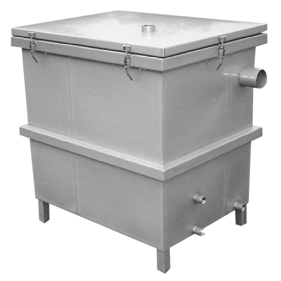
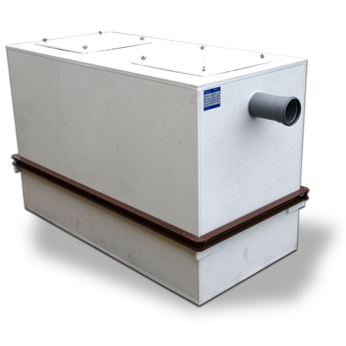
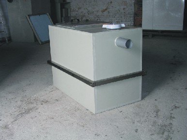
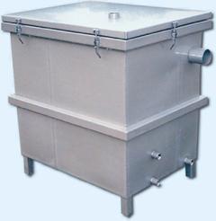
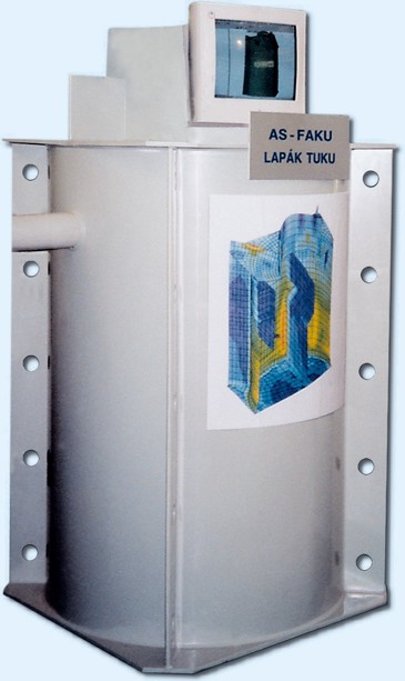
AS-FAKU FR - rectangular, designed for free installation in a room
-
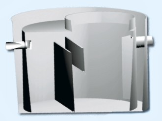
AS-FAKU EO/PB - circular, double-jacketed design, for in-ground installation
-
AS-FAKU EO/PB/SV - circular, double-jacketed design, for in-ground installation below the groundwater table
-
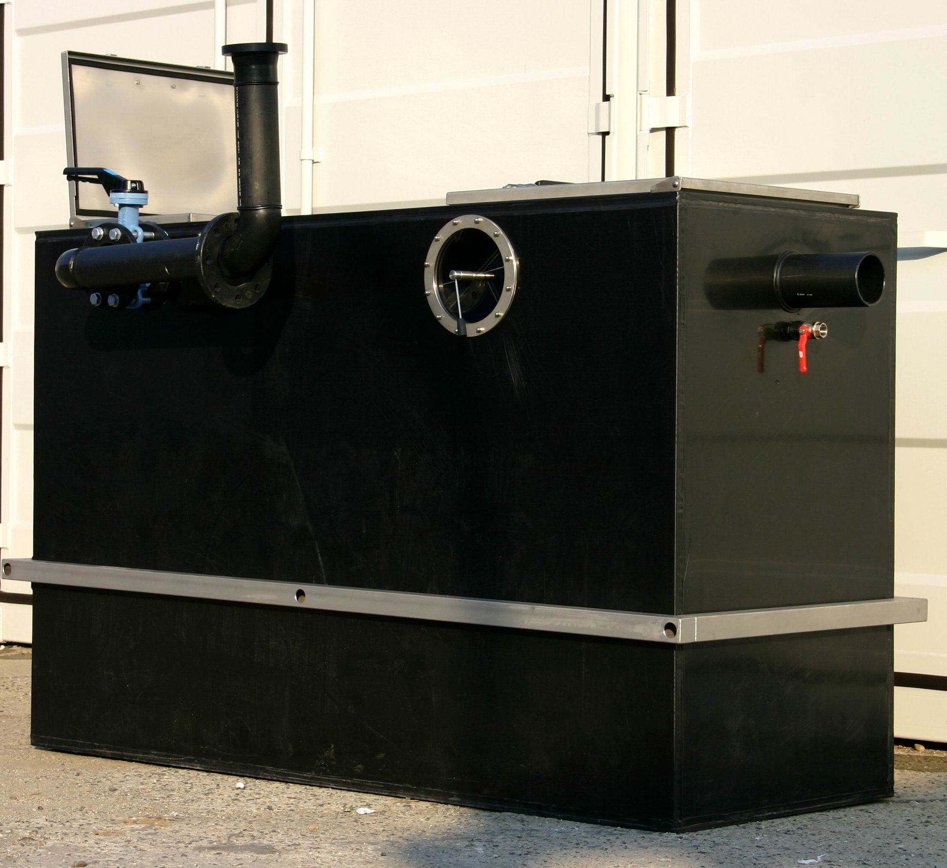
AS-FAKU FOZ/MANUAL - a grease trap with mechanical equipment for pumping grease, with subsequent rinsing and equipped with manual control. The trap is designed for room installation
-
AS-FAKU/AUTO - similar to the previous type, but with fully programmable automatic control
Depending on the number of meals a day, a suitable device can be approximately specified as follows:
up to 200....................size NS 2
up to 200 - 400 ...........size NS 4
up to 400 - 600 ...........size NS 7
AS-FAKU ER / FR
AS-FAKU ER - rectangular - for in-ground installation
The grease traps of the ER type are designed to be buried in the ground, for connection to the external sewerage system. Their design enables installation on a concrete slab, and in the case of self-supporting versions, direct embedding in gravel-sand without concreting, so long as the trap cannot move, is positioned in a green area, and the groundwater table is not high.
AS-FAKU FR - rectangular - for free installation in a room
The grease traps of the FR type are designed for free connection to sewerage pipes in basement rooms, cellars, etc.
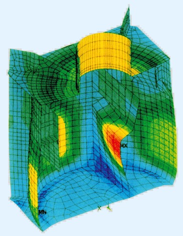
Examples of the static calculations for the standard we supply for each type range
GREASE TRAPS FOR IN-GROUND INSTALLATION
|
Type
|
Nom. size
|
Total dimensions
|
No. of inlets
|
Inlet height
|
Outlet height
|
Weight
|
|
|
[NS]
|
L x W x H [mm]
|
[pc]
|
Hv [mm] (DN)
|
Ho [mm] (DN)
|
[kg]
|
|
1 ER
|
1
|
1040 x 700 x 1040
|
1
|
790 (100)
|
720 (100)
|
90
|
|
2 ER
|
2
|
1360 x 1000 x 1160
|
1
|
900 (100)
|
830 (100)
|
130
|
|
4 ER
|
4
|
2660 x 1000 x 1160
|
2
|
900 (100)
|
830 (100)
|
350
|
|
5 ER
|
5
|
3160 x 1000 x 1260
|
2
|
900 (125)
|
830 (125)
|
390
|
|
7 ER
|
7
|
4160 x 1000 x 1260
|
2
|
900 (125)
|
830 (125)
|
530
|
|
8 ER
|
8
|
3160 x 1500 x 1260
|
2
|
900 (150)
|
830 (150)
|
580
|
|
10 ER
|
10
|
3660 x 1500 x 1260
|
2
|
950 (150)
|
880 (150)
|
650
|
|
15 ER
|
15
|
3660 x 2000 x 1660
|
2
|
1170 (200)
|
1100 (200)
|
840
|
|
20 ER
|
20
|
4660 x 2000 x 1660
|
2
|
1170 (200)
|
1100 (200)
|
950
|
|
25 ER
|
25
|
5660 x 2000 x 1660
|
2
|
1170 (200)
|
1100 (200)
|
1100
|
GREASE TRAPS FOR FREE INSTALLATION ON THE FLOOR
|
Type
|
Nom. size
|
Total dimensions
|
No. of inlets
|
Inlet height
|
Outlet height
|
Weight
|
|
|
[NS]
|
L x W x H [mm]
|
[ks]
|
Hv [mm] (DN)
|
Ho [mm] (DN)
|
[kg]
|
|
1 FR
|
1
|
1040 x 750 x 1040
|
1
|
790 (100)
|
720 (100)
|
95
|
|
2 FR
|
2
|
1540 x 750 x 1040
|
1
|
820 (100)
|
750 (100)
|
135
|
|
4 FR
|
4
|
3100 x 750 x 1340
|
2
|
970 (100)
|
900 (100)
|
300
|
|
5 FR
|
5
|
3300 x 750 x 1340
|
2
|
970 (125)
|
900 (125)
|
330
|
|
7 FR
|
7
|
3280 x 1600 x 1340
|
3
|
1070 (125)
|
1000 (125)
|
480
|
|
8 FR
|
8
|
3380 x 1600 x 1340
|
3
|
1070 (150)
|
1000 (150)
|
530
|
|
10 FR
|
10
|
4000 x 1600 x 1340
|
3
|
1070 (150)
|
1000 (150)
|
570
|
AS-FAKU EO / PB
DOUBLE-JACKETED DESIGN FOR IN-GROUND INSTALLATION ABOVE THE GROUNDWATER TABLE
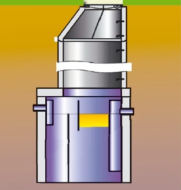 AS-FAKU 4EO/PB
The double-jacketed grease traps are delivered as devices designed for embedding in concrete on site, after installation, in an excavation where the plastic skeleton serves as sacrificial formwork for pouring the concrete mixture into the space between the jackets. After installation (concreting) the load-bearing capacity of the trap tank is secured with concrete, and original plastic shell ensures that it is leak proof.
The double-jacketed tank of the grease trap is equipped with the necessary concreting reinforcement, fixed to the plastic structure with the prescribed thickness of the concrete covering layer.
After the installation, the grease trap is waterproof, within the meaning of the requirements of ČSN 750905.
Advantages of the DOUBLE-JACKETED tank system:
-
Low weight of the equipment (transport, installation)
-
Concreting on the spot, without the installation of formwork and reinforcement
-
Exact position of the reinforcement fixed to the plastic jacket
-
100% protection from concrete corrosion caused by aggressive groundwater
-
100% leak-proof tank
-
Static sizing of the concrete lining depending on the place of installation (the traps are normally designed for static loading by soil pressure with the footing bottom at the depth of 5m and medium-weight vehicular traffic)
GREASE TRAPS …EO/PB FOR INSTALLATION ABOVE THE GROUNDWATER TABLE
|
Type
|
Nom. Size
|
Diameters [mm]
|
No. of tanks
|
DN
|
Tank height
|
Inlet height
|
Outlet height
|
Weight
|
Total concrete volume
|
|
|
[NS]
|
D / D1
|
D2 / D3
|
[pc]
|
[mm]
|
H [mm]
|
Hv [mm]
|
Ho [mm]
|
[kg]
|
[m
3
]
|
|
1 EO
|
1
|
950 / 1254
|
-
|
1
|
100
|
1090
|
790
|
720
|
95
|
0,54
|
|
2 EO
|
2
|
1200 / 1524
|
-
|
1
|
100
|
1190
|
790
|
720
|
165
|
0,81
|
|
4 EO
|
4
|
1600 / 1932
|
-
|
1
|
100
|
1290
|
890
|
820
|
280
|
1,41
|
|
5 EO
|
5
|
1800 / 2132
|
-
|
1
|
125
|
1290
|
890
|
820
|
390
|
1,62
|
|
7 EO
|
7
|
2000 / 2332
|
-
|
1
|
125
|
1390
|
990
|
920
|
430
|
1,97
|
|
8 EO
|
8
|
2100 / 2432
|
-
|
1
|
150
|
1390
|
990
|
920
|
480
|
2,08
|
|
10 EO
|
10
|
1200 / 1532
|
1904 / 2236
|
2
|
150
|
1390
|
990
|
920
|
180+410
|
3,02
|
|
15 EO
|
15
|
1520 / 1852
|
2180 / 2512
|
2
|
200
|
1540
|
1090
|
1020
|
290+530
|
4,10
|
|
20 EO
|
20
|
1760 / 2092
|
2680 / 3012
|
2
|
200
|
1540
|
1090
|
1020
|
340+610
|
5,20
|
|
25 EO
|
25
|
1920 / 2252
|
2880 / 3212
|
2
|
200
|
1540
|
1090
|
1020
|
390+690
|
5,70
|
AS - FAKU EO / PB / SV
DOUBLE-JACKETED DESIGN FOR INSTALLATION BELOW THE GROUNDWATER TABLE
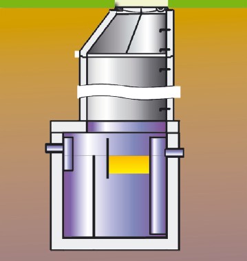 AS-FAKU 4EO/PB/SV
The design of the tanks of these grease traps combines the advantages of plastic and concrete. The basic plastic double-jacketed tank makes use of characteristics of plastic (low weight, waterproof, chemical resistance) and at the same time acts as the carrier for the reinforcement of the future concrete lining between the jackets.
After the concreting of the inner space between the jackets, the tank acquires the static properties of concrete tanks (load-bearing capacity and resistance to soil pressure, with the footing bottom at the standard depth of 5 m) and loading by medium-weight vehicular traffic.
The plastic walls perfectly protect the concrete structure from the aggressiveness of local wastewater and potential aggressiveness of groundwater.
The innovation of the design lies in combining the advantages of plastic and concrete in the tank structure and eliminating the existing disadvantages:
-
Permeability of concrete and not always reliable waterproofing
-
Corrosion of concrete in aggressive water and necessity of additional tank insulation
-
Limitation of the static dimensioning of plastic and its lower load-bearing capacity, with regard to the installation depth and groundwater table
GREASE TRAPS …EO/PB/SV FOR INSTALLATION BELOW THE GROUNDWATER TABLE
|
Type
|
Nom. Size
|
Diameters [mm]
|
No. of tanks
|
DN
|
Tank height
|
Inlet height
|
Outlet height
|
Weight
|
Total concrete volume
|
|
|
[NS]
|
D / D1
|
D2 / D3
|
[pc]
|
[mm]
|
H [mm]
|
Hv [mm]
|
Ho [mm]
|
[kg]
|
[m
3
]
|
|
1 EO
|
1
|
950 / 1274
|
-
|
1
|
100
|
1240
|
940
|
870
|
120
|
0,73
|
|
2 EO
|
2
|
1200 / 1524
|
-
|
1
|
100
|
1340
|
940
|
870
|
195
|
1,09
|
|
4 EO
|
4
|
1600 / 1932
|
-
|
1
|
100
|
1440
|
1040
|
970
|
310
|
1,85
|
|
5 EO
|
5
|
1800 / 2132
|
-
|
1
|
125
|
1440
|
1040
|
970
|
440
|
2,15
|
|
7 EO
|
7
|
2000 / 2332
|
-
|
1
|
125
|
1540
|
1140
|
1070
|
510
|
2,61
|
|
8 EO
|
8
|
2100 / 2432
|
-
|
1
|
150
|
1540
|
1140
|
1070
|
570
|
2,78
|
|
10 EO
|
10
|
1200 / 1532
|
1904 / 2236
|
2
|
150
|
1540
|
1140
|
1070
|
230+490
|
3,67
|
|
15 EO
|
15
|
1520 / 1852
|
2180 / 2512
|
2
|
200
|
1690
|
1240
|
1170
|
340+600
|
4,90
|
|
20 EO
|
20
|
1760 / 2092
|
2680 / 3012
|
2
|
200
|
1690
|
1240
|
1170
|
390+700
|
6,20
|
|
25 EO
|
25
|
1920 / 2252
|
2880 / 3212
|
2
|
200
|
1690
|
1240
|
1170
|
460+780
|
6,90
|