
AS-POMPE
Les stations de pompage domestiques AS-PUMP (relevage, puisards) sont conçus pour le pompage des eaux usées, des eaux pluviales et des eaux souterraines, sous-pression ou par écoulement gravitaire…
Les stations de pompage domestiques AS-PUMP (relevage, puisards) sont conçus pour le pompage des eaux usées, des eaux pluviales et des eaux souterraines, sous-pression ou par écoulement gravitaire…
The AS-PUMP pumping shafts are designed for re-pumping wastewater, rainwater, and groundwater or other liquids from the household and other structures to pressure or gravity sewerage.
They are made of polypropylene, which guarantees their chemical resistance; however, they are not suitable for re-pumping flammability class I and II liquids. On request, pumping shafts can be supplied certified as to their hygienic suitability for food processing purposes. Pumping shafts can be installed both outdoors and on the technical floors of buildings or basements, as free standing on the floor.
| AS–PUMP D1/H EO/PPn Pumping Shafts | |
| Design | Free-standing device |
| Installation | Dry (groundwater table below the footing bottom) |
| Diagram | → → |
| Tank shape | EO – cylindrical, underground |
| Tank design | PPn – all-plastic structure – not self-supporting |
| Static design | Self-supporting after embedding in concrete |
| Type | Tank diameter | Tank height | Inlet shaft height | Transport weight |
|
D
[mm] |
H
[mm] |
Vn
[mm] |
[kg] | |
| AS PUMP 800/1,500 | 800 | 1,500 | max. 500 | 130 |
| AS PUMP 800/2,000 | 800 | 2,000 | max. 500 | 145 |
| AS PUMP 800/2,500 | 800 | 2,500 | max. 500 | 160 |
| AS PUMP 800/3,000 | 800 | 3,000 | max. 500 | 175 |
| AS PUMP 960/1,500 | 960 | 1,500 | max. 500 | 160 |
| AS PUMP 960/2,000 | 960 | 2,000 | max. 500 | 175 |
| AS PUMP 960/2,500 | 960 | 2,500 | max. 500 | 190 |
| AS PUMP 960/3,000 | 960 | 3,000 | max. 500 | 205 |
| AS PUMP 1,280/1,500 | 1,280 | 1,500 | max. 500 | 180 |
| AS PUMP 1,280/2,000 | 1,280 | 2,000 | max. 500 | 200 |
| AS PUMP 1,280/2,500 | 1,280 | 2,500 | max. 500 | 220 |
| AS PUMP 1,280/3,000 | 1,280 | 3,000 | max. 500 | 240 |
| AS PUMP 1,520/1,500 | 1,520 | 1,500 | max. 500 | 200 |
| AS PUMP 1,520/2,000 | 1,520 | 2,000 | max. 500 | 230 |
| AS PUMP 1,520/2,500 | 1,520 | 2,500 | max. 500 | 260 |
| AS PUMP 1,520/3,000 | 1,520 | 3,000 | max. 500 | 290 |
| AS PUMP 2,000/1,500 | 2,000 | 1,500 | max. 500 | 260 |
| AS PUMP 2,000/2,000 | 2,000 | 2,000 | max. 500 | 300 |
| AS PUMP 2,000/2,500 | 2,000 | 2,500 | max. 500 | 340 |
| AS PUMP 2,000/3,000 | 2,000 | 3,000 | max. 500 | 380 |
| AS–PUMP D1/H EO/PPs Pumping Shafts | |
| Design | Free-standing device |
| Installation | Dry (groundwater table below the footing bottom) |
| Diagram | → → |
| Tank shape | EO – cylindrical, underground |
| Tank design | PPn – all-plastic structure – self-supporting |
| Static design | Self supporting after soil backfilling |
| Type | Tank diameter | Tank height | Inlet shaft height | Transport weight |
|
D
[mm] |
H
[mm] |
Vn
[mm] |
[kg] | |
| AS PUMP 800/1500 | 800 | 1,500 | max. 330 | 140 |
| AS PUMP 800/2000 | 800 | 2,000 | max. 330 | 155 |
| AS PUMP 800/2500 | 800 | 2,500 | max. 330 | 170 |
| AS PUMP 800/3000 | 800 | 3,000 | max. 330 | 185 |
| AS PUMP 960/1500 | 960 | 1,500 | max. 330 | 170 |
| AS PUMP 960/2000 | 960 | 2,000 | max. 330 | 185 |
| AS PUMP 960/2500 | 960 | 2,500 | max. 330 | 200 |
| AS PUMP 960/3000 | 960 | 3,000 | max. 330 | 210 |
| AS PUMP 1,280/1,500 | 1,280 | 1,500 | max. 330 | 190 |
| AS PUMP 1,280/2,000 | 1,280 | 2,000 | max. 330 | 210 |
| AS PUMP 1,280/2,500 | 1,280 | 2,500 | max. 330 | 230 |
| AS PUMP 1,280/3,000 | 1,280 | 3,000 | max. 330 | 250 |
| AS–PUMP D1/H EO/PB Pumping Shafts | |
| Design | Free-standing device |
| Installation | Above the groundwater table |
| Diagram | → → |
| Tank shape | EO – cylindrical, underground |
| Tank design | PB – double-jacketed |
| Static design |
Self-supporting after concreting –
the tank is completely prepared for concreting on site, including concrete reinforcement |
| Type | Inner diameter of the tank | Outer diameter of the tank | Tank height | Concrete volume | Tank wall thickness | Transport weight |
|
D
[mm] |
D1
[mm] |
H
[mm] |
Vb
[m 3 ] |
s [mm] |
[kg] | |
| AS PUMP 1,130/1,500 | 800 | 1,130 | 1,500 | 0.86 | 150 | 220 |
| AS PUMP 1,130/2,000 | 800 | 1,130 | 2,000 | 1.10 | 150 | 260 |
| AS PUMP 1,130/2,500 | 800 | 1,130 | 2,500 | 1.34 | 150 | 300 |
| AS PUMP 1,130/3,000 | 800 | 1,130 | 3,000 | 1.58 | 150 | 340 |
| AS PUMP 1,290/1,500 | 960 | 1,290 | 1,500 | 1.10 | 150 | 250 |
| AS PUMP 1,290/2,000 | 960 | 1,290 | 2,000 | 1.46 | 150 | 290 |
| AS PUMP 1,290/2,500 | 960 | 1,290 | 2,500 | 1.83 | 150 | 330 |
| AS PUMP 1,290/3,000 | 960 | 1,290 | 3,000 | 2.18 | 150 | 370 |
| AS PUMP 1,530/1,500 | 1,200 | 1,530 | 1,500 | 1.37 | 150 | 280 |
| AS PUMP 1,530/2,000 | 1,200 | 1,530 | 2,000 | 1.72 | 150 | 320 |
| AS PUMP 1,530/2,500 | 1,200 | 1,530 | 2,500 | 2.07 | 150 | 350 |
| AS PUMP 1,530/3,000 | 1,200 | 1,530 | 3,000 | 2.42 | 150 | 400 |
| AS PUMP 1,770/1,500 | 1,440 | 1,770 | 1,500 | 1.56 | 150 | 290 |
| AS PUMP 1,770/2,000 | 1,440 | 1,770 | 2,000 | 1.96 | 150 | 347 |
| AS PUMP 1,770/2,500 | 1,440 | 1,770 | 2,500 | 2.36 | 150 | 427 |
| AS PUMP 1,770/3,000 | 1,440 | 1,770 | 3,000 | 2.76 | 150 | 500 |
| AS PUMP 2,250/1,500 | 1,920 | 2,250 | 1,500 | 2.20 | 150 | 490 |
| AS PUMP 2,250/2,000 | 1,920 | 2,250 | 2,000 | 2.73 | 150 | 580 |
| AS PUMP 2,250/2,500 | 1,920 | 2,250 | 2,500 | 3.26 | 150 | 660 |
| AS PUMP 2,250/3,000 | 1,920 | 2,250 | 3,000 | 3.80 | 150 | 735 |
| AS PUMP 2,710/1,500 | 2,380 | 2,710 | 1,500 | 2.80 | 150 | 665 |
| AS PUMP 2,710/2,000 | 2,380 | 2,710 | 2,000 | 3.50 | 150 | 765 |
| AS PUMP 2,710/2,500 | 2,380 | 2,710 | 2,500 | 4.10 | 150 | 870 |
| AS PUMP 2,710/3,000 | 2,380 | 2,710 | 3,000 | 4.60 | 150 | 1,000 |
| AS PUMP 3,210/1,500 | 2,880 | 3,210 | 1,500 | 3.44 | 150 | 765 |
| AS PUMP 3,210/2,000 | 2,880 | 3,210 | 2,000 | 4.18 | 150 | 865 |
| AS PUMP 3,210/2,500 | 2,880 | 3,210 | 2,500 | 4.92 | 150 | 970 |
| AS PUMP 3,210/3,000 | 2,800 | 3,210 | 3,000 | 5.66 | 150 | 1,100 |
| AS–PUMP D1/H EO/PB - SV Pumping Shafts | |
| Design | Free-standing device |
| Installation | Below the groundwater table |
| Diagram | → → |
| Tank shape | EO – cylindrical, underground |
| Tank design | PB – double-jacketed |
| Static design | Self-supporting after concreting - the tank is completely prepared for concreting on site, incl. concrete reinforcement, sized for the max. groundwater table up to the outlet level |
| Type | Inner diameter of the tank | Outer diameter of the tank | Tank height | Concrete volume | Tank wall thickness | Transport weight |
|
D
[mm] |
D1
[mm] |
H
[mm] |
Vb
[m 3 ] |
s [mm] |
[kg] | |
| AS PUMP 1,130/1,500 | 800 | 1,130 | 1,500 | 1.10 | 150 | 260 |
| AS PUMP 1,130/2,000 | 800 | 1,130 | 2,000 | 1.24 | 150 | 300 |
| AS PUMP 1,130/2,500 | 800 | 1,130 | 2,500 | 1.48 | 150 | 340 |
| AS PUMP 1,130/3,000 | 800 | 1,130 | 3,000 | 1.95 | 150 | 380 |
| AS PUMP 1,290/1,500 | 960 | 1,290 | 1,500 | 1.35 | 150 | 300 |
| AS PUMP 1,290/2,000 | 960 | 1,290 | 2,000 | 1.68 | 150 | 340 |
| AS PUMP 1,290/2,500 | 960 | 1,290 | 2,500 | 2.05 | 150 | 380 |
| AS PUMP 1,290/3,000 | 960 | 1,290 | 3,000 | 2.40 | 150 | 420 |
| AS PUMP 1,530/1,500 | 1,200 | 1,530 | 1,500 | 1.67 | 150 | 350 |
| AS PUMP 1,530/2,000 | 1,200 | 1,530 | 2,000 | 2.10 | 150 | 390 |
| AS PUMP 1,530/2,500 | 1,200 | 1,530 | 2,500 | 2.40 | 150 | 420 |
| AS PUMP 1,530/3,000 | 1,200 | 1,530 | 3,000 | 2.80 | 150 | 470 |
| AS PUMP 1,770/1,500 | 1,440 | 1,770 | 1,500 | 1.96 | 150 | 370 |
| AS PUMP 1,770/2,000 | 1,440 | 1,770 | 2,000 | 2.30 | 150 | 427 |
| AS PUMP 1,770/2,500 | 1,440 | 1,770 | 2,500 | 2.80 | 150 | 507 |
| AS PUMP 1,770/3,000 | 1,440 | 1,770 | 3,000 | 3.15 | 150 | 580 |
| AS PUMP 2,250/1,500 | 1,920 | 2,250 | 1,500 | 2.80 | 150 | 580 |
| AS PUMP 2,250/2,000 | 1,920 | 2,250 | 2,000 | 3.35 | 150 | 670 |
| AS PUMP 2,250/2,500 | 1,920 | 2,250 | 2,500 | 3.86 | 150 | 750 |
| AS PUMP 2,250/3,000 | 1,920 | 2,250 | 3,000 | 4.40 | 150 | 825 |
| AS PUMP 2,710/1,500 | 2,380 | 2,710 | 1,500 | 3.90 | 150 | 705 |
| AS PUMP 2,710/2,000 | 2,380 | 2,710 | 2,000 | 4.60 | 150 | 805 |
| AS PUMP 2,710/2,500 | 2,380 | 2,710 | 2,500 | 5.20 | 150 | 910 |
| AS PUMP 2,710/3,000 | 2,380 | 2,710 | 3,000 | 5.70 | 150 | 1,050 |
| AS PUMP 3,210/1,500 | 2,880 | 3,210 | 1,500 | 4.65 | 150 | 915 |
| AS PUMP 3,210/2,000 | 2,880 | 3,210 | 2,000 | 5.40 | 150 | 1,015 |
| AS PUMP 3,210/2,500 | 2,880 | 3,210 | 2,500 | 6.15 | 150 | 1,120 |
| AS PUMP 3,210/3,000 | 2,800 | 3,210 | 3,000 | 6.90 | 150 | 1,250 |
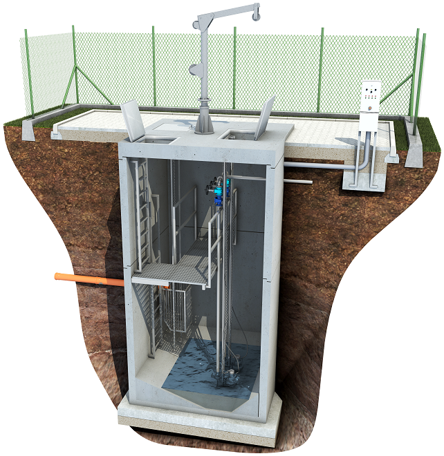
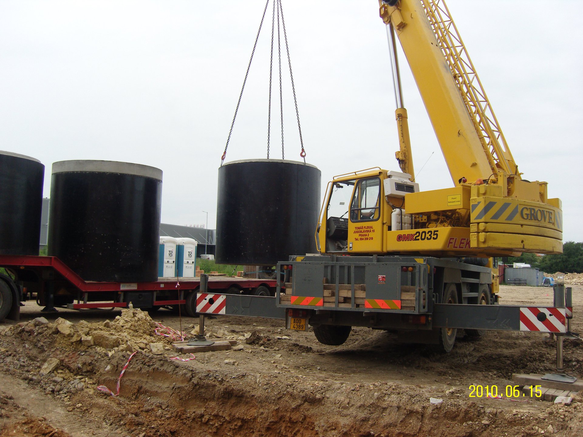
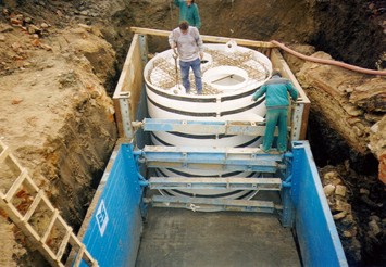
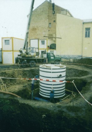
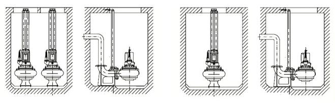 Pumping Shafts - Installation Example No. 1
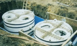
Pumping Shafts - Installation Example No. 2
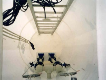
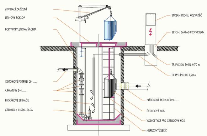
The pumping shafts are equipped with pumps of various types, as a standard feature – KSB, FLYGHT, SIGMA LUTÍN, WILO-EMU, GRUNDFOS (at the customer's request). The tank can be equipped with one or two pumps, of which one or both are generally comminution ones (the switching command is indicated in the technological diagram). Individual levels are signalled by floater switches or an ultrasonic sensor. The delivery of the pumping station includes the switchboard, incl. control electronics. The pumps are designed individually on the basis of input parameters.
| Electric switchboards for two pumps | Pillar - for free installation in terrain | ||||||
| SED 54 zP | SED 54 szP | SED 54 USzP | SED 54 USzhP | SED 54 USzP–u | SED 54 UGzP | SED 54 UTzP | |
| Plastic pillar | ● | ● | ● | ● | ● | ● | ● |
| Full plastic cabinet - wall-mounted design | |||||||
| No signalling | ● | ||||||
| Local light signalling: pump operation and failure | ● | ● | ● | ● | ● | ● | |
| Local acoustic signalling: max. level | ● | ● | ● | ● | ● | ● | ● |
| Output for remote transmission of remote statuses: | ● | ● | ● | ● | ● | ||
| – Operation and failure of M1, M2 | ● | ● | ● | ● | ● | ||
| – Pumping station overfilling | ● | ● | ● | ● | ● | ||
| – Voltage loss in the switchboard | ● | ● | ● | ● | ● | ||
| Pump operation selection automatic/manual | ● | ● | ● | ● | ● | ● | ● |
| Automatic mutual replacement of pumps in case of a failure | ● | ● | ● | ● | ● | ● | ● |
| Service socket 230 V | ● | ● | ● | ● | ● | ● | ● |
| Service socket 400 V | ● | ● | ● | ● | ● | ● | |
| Summation hour meter for each pump | ● | ● | ● | ● | |||
| Mains – O – power supply switch | ● | ● | ● | ● | |||
| Remote data transmission via GSM | ● | ||||||
| Place for the ultrasonic evaluation unit | ● | ● | ● | ||||
| Place for telemetry, 800 x 600 mm | |||||||
| Complete documentation of switchboard wiring | ● | ● | ● | ● | ● | ● | ● |
| Initial inspection | ● | ● | ● | ● | ● | ● | ● |
| Electric switchboards for one pump | Pillar - for free installation in terrain | |||
| SED 53 P | SED 54 sP | SED 54 USP | SED 54 USZP | |
| Plastic pillar | ● | ● | ● | ● |
| Full plastic cabinet - wall-mounted design | ||||
| Local light signalling: pump operation and failure | ● | ● | ● | |
| Local acoustic signalling: max. level | ● | ● | ● | ● |
| Output for remote transmission of remote statuses: | ● | ● | ||
| – operation and failure of M1, M2 | ● | ● | ||
| – pumping station overfilling | ● | ● | ||
| – voltage loss in the switchboard | ● | ● | ||
| Pump operation selection automatic/manual | ● | ● | ● | ● |
| Service socket 230 V | ● | ● | ● | ● |
| Service socket 400 V | ● | ● | ● | |
| Summation hour meter | ● | |||
| Complete documentation of switchboard wiring | ● | ● | ● | ● |
| Initial inspection | ● | ● | ● | ● |
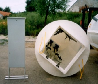
AS-PUMP pumping shaft, H = 1,500 mm, D = 800 mm, with an inlet shaft 600 x 600 mm (or 900 x 600 mm), Vn = 450 mm, and a cast-iron cover, with an inlet adapted to KT 100 and outlet to PE 2", equipped with comminution pumps of the SIGMA 40 GFZU type, 2 units, defining the ground plan and height arrangement of the inlet and outlet.
Or you can have a design of the pumping shaft (accumulation size and pump type) prepared by a specialist in accordance with the basic parameters:
AS-PUMP 2000/4600 (beton), municipality: Pardubice (apartment building), CZ
AS-PUMP 2530/4000 EO/ PB/SV, municipality: Unetice (sewerage), CZ
AS-PUMP 2240/4900 EO/PB/SV, municipality: Malé Hoštice (sewerage), CZ
AS-PUMP 2000/3000 (beton), Municipality: Stochov (TESCO), CZ
AS-PUMP 1760/4000 EO/PB-SV, municipality: Žatec (Solar Turbines EAME), CZ
AS-PUMP 2240/2500 EO/PB/SV, municipality: Kladno (DPS), CZ
AS-PUMP 1760/4560 EO/PB/SV, municipality: Nosislav (sewerage), CZ
AS-PUMP 2250/3300 EO/PB-SV, municipality: Zábřeh na Moravě (sewerage), CZ
AS-PUMP 1760/4850 EO/PB/SV, municipality: Pardubice (airport), CZ
AS-PUMP 2250/5000 EO/PB/ SV, municipality: Pardubice (airport), CZ
AS-PUMP 2300/4700 EO/B/SV, municipality: Čelákovice (TESCO), CZ
AS-PUMP 2300/4700 EO/B/SV, municipality: Čelákovice (TESCO), CZ
AS-PUMP 1800/3000 EO/B/SV, municipality: Čelákovice (TESCO), CZ
AS-PUMP 3200/4000 EO/PB/SV, municipality: Havířov (Globus), CZ
AS-PUMP 1900x1900x2813 ER / PPN, municipality: Brno (VMO Dobrovského tunely), CZ
Process units DN80, municipality: Prachovník (sewerage), CZ
AS-PUMP 1760/2960 EO / PB / SV, municipality:: Sloup - Sošůvka (sewerage), CZ
AS-PUMP 2240/6000 EO / PB / SV, municipality: Břeclav (Alca plast), CZ
AS-PUMP 1760/5000 EO / PB / SV, municipality: Vítkovice (sewerage), CZ
AS-PUMP 2240/3500 EO / PB / SV, municipality:: Vysoká Pec (sewerage), CZ
AS-PUMP 1760/3500 EO / PB / SV, municipality: Sudoměřice (sewerage), CZ
AS-PUMP 1760/4500 EO / PB / SV, municipality: Kravaře (castle), CZ
AS-PUMP 2240/3500 EO / PB / SV, municipality: Komořany (sewerage), CZ
Technological systems DN 80, Municipality: Mariánské Lázně (TESCO), CZ
AS-PUMP 2240/3000 EO/PB/SV, municipality: Mořkov (sewerage), CZ
AS-PUMP 2240/3000 EO/PB/SV, municipality: Česká Bělá (sewerage), CZ
AS-PUMP 2240/3000 EO/PB/SV, municipality: Česká Bělá (sewerage), CZ
AS-PUMP 1770/2000 EO/PB/SV, municipality: Česká Bělá (sewerage), CZ
AS-PUMP 2240/3000 EO/PB/SV, municipality: Okříšky (CTPark), CZ
AS-PUMP 2240/4900 EO/PB/SV, municipality: Malé Hoštice (sewerage), CZ
AS-PUMP 2240/6000 EO/PB/SV, municipality: Břeclav, CZ
Technological outfit PS, municipality: Rovensko (sewerage), CZ
Technological outfit PS, municipality: Mladá Boleslav (VaK), CZ