The dehydrator is used for the thickening and subsequent dewatering of sludge. The equipment is small and lightweight and can work in automatic operation with minimal maintenance requirements. The device guarantees the thickening of activated sludge to at least 18% of dry matter, for sludge from municipal WWTPs.
The device is produced in several lines, and thanks to its low investment as well as operating costs, it is suitable mainly for industrial treatment plants and municipal treatment plants from 1,000 to 10,000 PE. Another great benefit of this device is the ability to thicken secondary sludge directly from the activation, which may eliminate the cost of the construction of storage tanks within the design of a new WWTP.
1. Reduction of construction costs
The dehydrator contains a thickening zone that eliminates the need of thickening the sludge before its inflow into the device. The dehydration drum forms a compact structure together with supplementary devices that allows you to minimize spatial requirements.
2. Reduction of operation costs
The dehydrator is designed in such a way that it is protected from clogging. This minimizes the requirements for rinsing water and operation. The energy consumption of the dehydrator is very low (0.3 - 2.15 kW).
3. Efficient dewatering
The device dehydrates sludge with low dry matter concentration directly from the activation part and produces a sludge cake with the dry matter content of about 20 – 25%.
4. 24-hour automatic operation without attendance
The dehydrator is able to work in continuous automatic mode, incl. dosing of chemicals. The time requirements for its maintenance and operation are minimal (approx. 5 min/day).
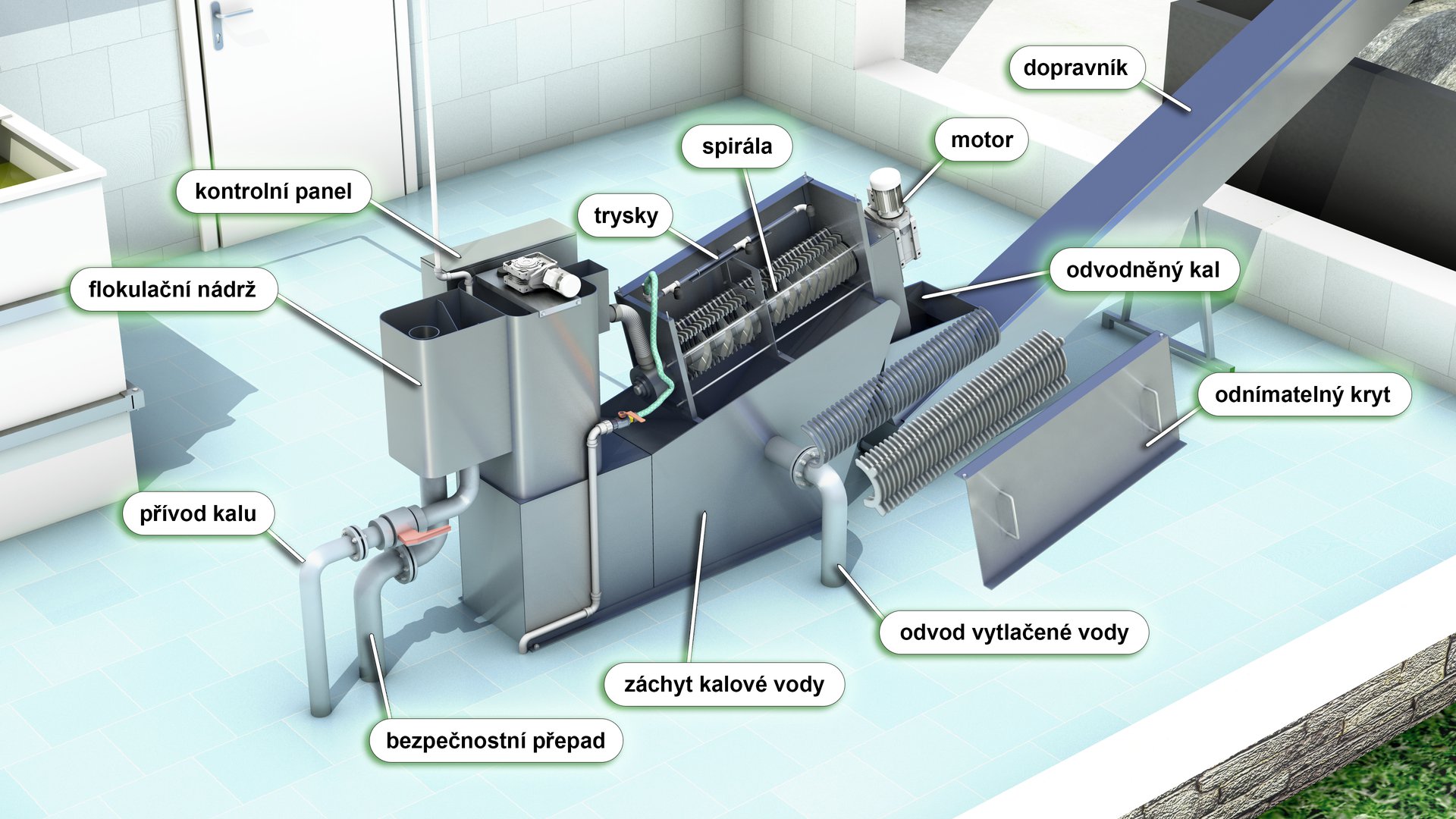
The dehydration drum consists of a volute rotating at a constant speed under a layer of fixed and movable lamellas. The volute pushes the edges of the movable lamellas that continuously move in the gaps between the fixed lamellas during the rotation of the volute. In this way the space inside is cleaned, thus preventing clogging. Sludge water is then drained through the gaps between the lamellas. The gaps between the lamellas get gradually smaller towards the place where the sludge cake is removed. The gap between the lamellas is first 0.5 mm in the thickening zone, 0.3 mm in the dewatering zone, and at the end the gap is 0.15 mm. The end compression plate increases pressure onto the sludge cake to achieve more efficient sludge dewatering.
| 131 | 201 | 202 | 301 | 302 | 303 | ||
| Max. flow (dry matter of sludge 0,2 kg/l) | m 3 /hour | 3,0 | 4,5 | 9,0 | 15,0 | 30,0 | 45,0 |
| Mean value flow (dry matter of sludge 1 kg/l) | m 3 /hour | 1,0 | 1,5 | 3,0 | 5,0 | 10,0 | 15,0 |
| Min. flow (dry matter of sludge 5 kg/l) | m 3 /hour | 0,2 | 0,3 | 0,6 | 1,0 | 2,0 | 3,0 |
| Degree of draining | % | 18 | 18 | 18 | 18 | 18 | 18 |
| Dry matter production | kg/hour | 6-10 | 9-15 | 18-30 | 30-50 | 60-100 | 90-150 |
| Consumption of clean water | l/hour | 24 | 32 | 64 | 40 | 80 | 120 |
| Consumption of flocculant | l/hour | 20-45 | 30-70 | 60-135 | 100-225 | 200-450 | 300-675 |